Autonomous Arduino Vehicle
Design by Alexander Kaula and Andreas Schmidt.
Technical design class under the guidance of Prof. Tom Philipps.
Design von Alexander Kaula und Andreas Schmidt.
Technischer Entwurf unter Betreuung von Prof. Tom Philipps.
Assignment
Aufgabenstellung
Realization of an Arduino based vehicle, which drives autonomously through an unknown course. The vehicle should be as light and fast as possible.
Umsetzung eines Arduino basierenden Fahrzeuges, welches einen unbekannten Parcours autonom durchfährt. Das Fahrzeug sollte dabei möglichst leicht und schnell sein.


Project Progress
Projektverlauf
Since I had never worked with electronic components before and only had some HTML and CSS programming skills, this was a big challenge. In the first step we familiarized ourselves with the Arduino and its controls. A basic element of autonomous driving is object recognition or distance measurement. Therefore, we initially looked at various possibilities to realize this in a small and light scale for our project. Ultimately, the decision was made in favour of the HC-SR04 ultrasonic sensor, as it is very inexpensive, widespread and easy to control. The first test setup read out the distance and assigned the measured values to one of three distance ranges and switched on a green, yellow or red LED accordingly. These were the first steps with "if-else" equations.
In the next weeks we experimented with different motors. At first it was difficult to find an electric motor that had enough torque to accelerate the vehicle and also enough revs to achieve the fastest possible movement. During our research we then came across micro-torque generators. These are small electric motors that have a gearbox in front of them. There is a wide range of ratios, from 20 to almost 800 rpm.
After the motor had been defined, we started with the programming. In order for the vehicle to get enough information, we finally worked with three ultrasonic sensors. One in front and two on the sides. First, the vehicle was programmed to evade objects. This didn't turn out to be very helpful in our practice course, as the vehicle often turned around and drove back to the start. Finally we decided to program a wall follower. For example, it always stayed on the right side of the course and thus was able to clear the parcours 100% of the time. However, depending on the course, this can take a long time. Finally I had the idea to change the "if-else"-equation in such a way that the vehicle always moves to the longest distance. During the presentation of the intermediate results, this programming proved to be very efficient. Our vehicle was the fastest on the course.
(See the following video)
(See the following video)
Da ich zuvor noch nie mit Elektronik-Komponenten gearbeitet habe und bezüglich Programmierung nur etwas HTML und CSS konnte, war diese Aufgabe eine grosse Herausforderung. Im ersten Schritt machten wir uns mit dem Arduino und dessen Steuerung vertraut. Ein Grundelement des autonomen Fahrens ist die Objekterkennung bzw. Distanzmessung. Daher beschäftigten wir uns zunächst mit verschiedenen Möglichkeiten dies in einem kleinen und leichten Massstab für unser Projekt zu realisieren. Letzten Endes fiel die Entscheidung auf den HC-SR04 Ultraschallsensor, da dieser sehr günstig, weit verbreitet und gut anzusteuern ist. Der erste Testaufbau las die Distanz aus und ordnete die gemessene Werte einem von drei Distanzbereichen zu und schaltete dementsprechend eine grüne, gelbe oder rote LED an. Dies waren die ersten Schritte mit „if-else“-Gleichungen.
In den nächsten Wochen experimentierten wir mit verschiedenen Antrieben. Es war zunächst schwierig einen Elektromotor zu finden, welcher genügend Drehmoment hatte um das Fahrzeug zu Beschleunigen und des Weiteren genügend Drehzahl um eine möglichst schnelle Fortbewegung zu erzielen. Bei unserer Recherche stießen wir dann auf Micro-Drehmomentgeneratoren. Dies sind kleine Elektromotoren die ein Getriebe vorgesetzt haben. Hier gibt es eine große Bandbreite an Übersetzungen, von 20 bis fast 800 U/m.
Nachdem der Antrieb geklärt war, ging es an die Programmierung. Damit das Fahrzeug genug Informationen bekommt, arbeiteten wir letzten Endes mit drei Ultraschallsensoren. Einer vorne und zwei an den Seiten. Zunächst wurde das Fahrzeug so programmiert, dass es Objekten ausweicht. Dies stellte sich dann in unserem Übungsparcours als nicht sonderlich hilfreich heraus, da das Fahrzeug sich oft umgedrehte und wieder zum Start fuhr. Schließlich kamen wir darauf einen Wandfolger zu programmieren. Diese hielt sich z.B. immer an der rechten Seite des Parcours und fand somit zu 100% aus dem Parcours. Jedoch kann dies je nach Parcours sehr lange dauern. Schließlich kam ich auf die Idee die „if-else“-Gleichung so zu verändern, dass das Fahrzeug immer auf die weiteste Distanz zufährt. Bei der gemeinsamen Zwischenpräsentation erwies sich diese Programmierung als sehr effizient heraus. Unser Fahrzeug fuhr als schnellstes durch den Parcours.
(Siehe folgendes Video)
After the motor and the programming had been determined, we worked on the miniaturization of our structure. One of our goals was to create our own PCB, as we could save a lot of weight here. First we tried to mill a PCB. However, the smallest cutter with 1mm proved to be much too coarse. So we bought 0.1mm milling cutters and turned a fixture for the Datron spindle. This worked quite well, but the copper layer detached quickly with very narrow ribs.
In the next step we tried to etch the PCBs. (See the following video).
In this chemical process, a photosensitive layer on the PCB material is exposed to UV light. Then the unexposed part of the PCB is cured in a developing bath and the exposed part dissolves. The PCB is then etched in an iron chloride bath. The copper layer of the PCB, which is no longer covered by a protective layer, is dissolved in this step. The finished traces remain behind. The holes for the vias were then drilled and provided with hollow copper rivets and the PCB was cut to the finished size.
Nachdem nun der Antrieb und die Programmierung festgelegt waren, arbeiteten wir an der Miniaturisierung unseres Aufbaus. Ein Ziel von uns war es eine eigene Leiterplatte zu erstellen, da wir hier sehr viel Gewicht sparen könnten.
Zunächst versuchten wir eine Leiterplatte zu fräsen. Der kleinste Fräser mit 1mm erwies sich jedoch als viel zu grob. Daher kauften wir 0,1mm Fräser und drehten eine Aufnahme für die Datron Spindel. Dies funktionierte recht gut, jedoch löste sich die Kupferschicht bei sehr schmalen Stegen schnell ab. Im nächsten Schritt versuchten wir uns am Leiterplattenätzen. (Siehe folgendes Video).
In diesem chemischen Verfahren wird eine fotosensitive Schicht auf dem Leiterplattenmaterial unter UV Licht belichtet. Anschließend wird in einem Entwicklungsbad der unbelichtete Teil der Leiterplatte ausgehärtet und der belichtete Teil löst sich auf. Daraufhin wird die Leiterplatte in ein Eisenchlorid-Bad geätzt. Die Kupferschicht der Leiterplatte, welche nicht mehr durch eine Schutzschicht bedeckt ist, wird in diesem Schritt aufgelöst. Zurück bleiben die fertigen Leiterbahnen.
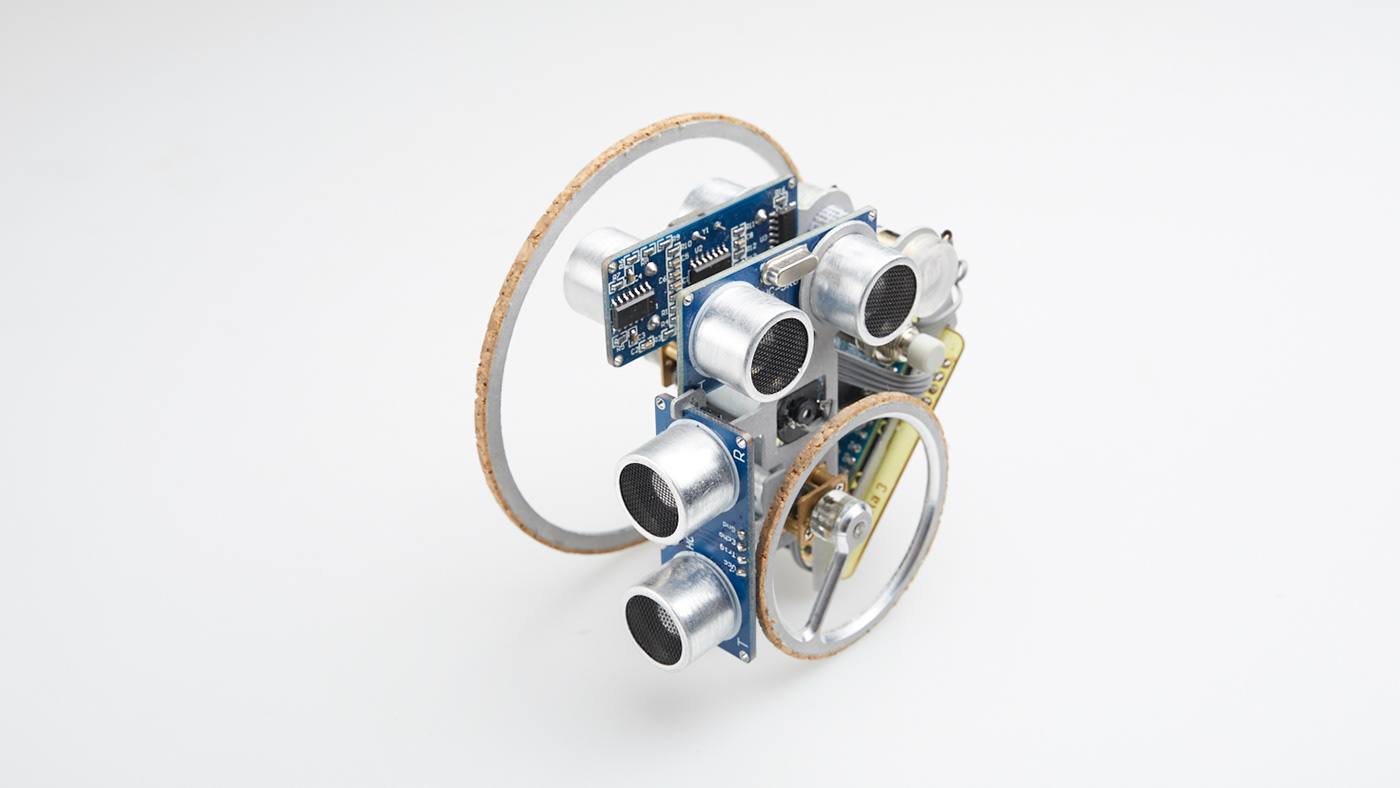
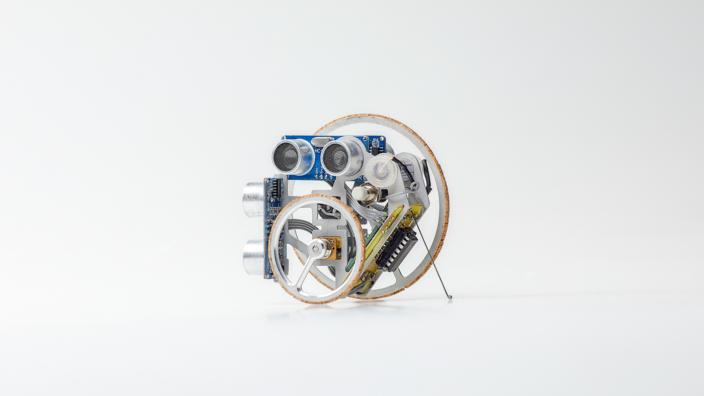
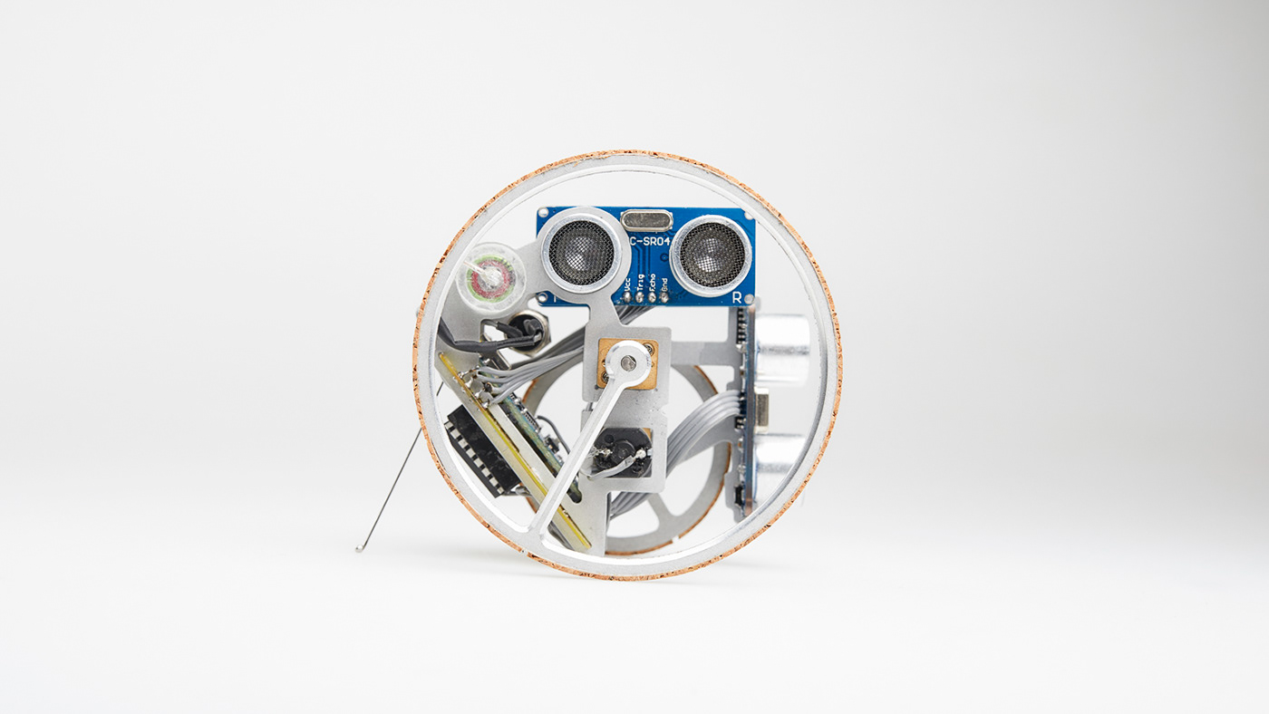
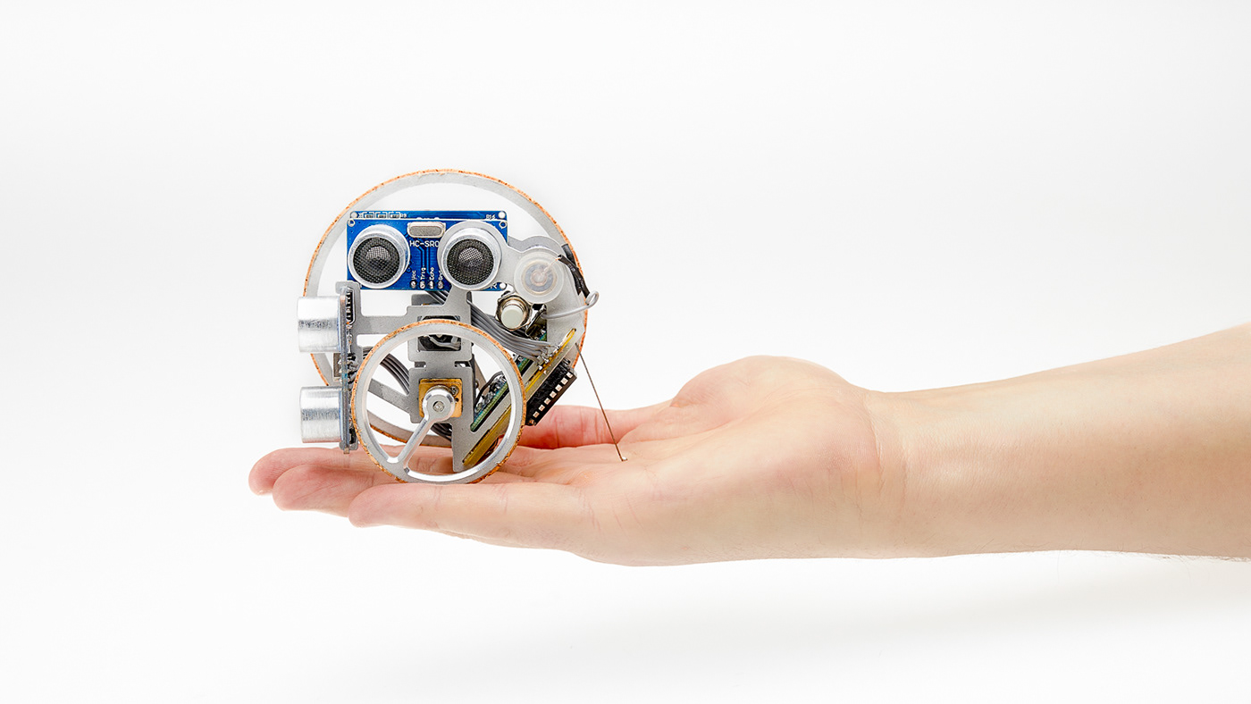
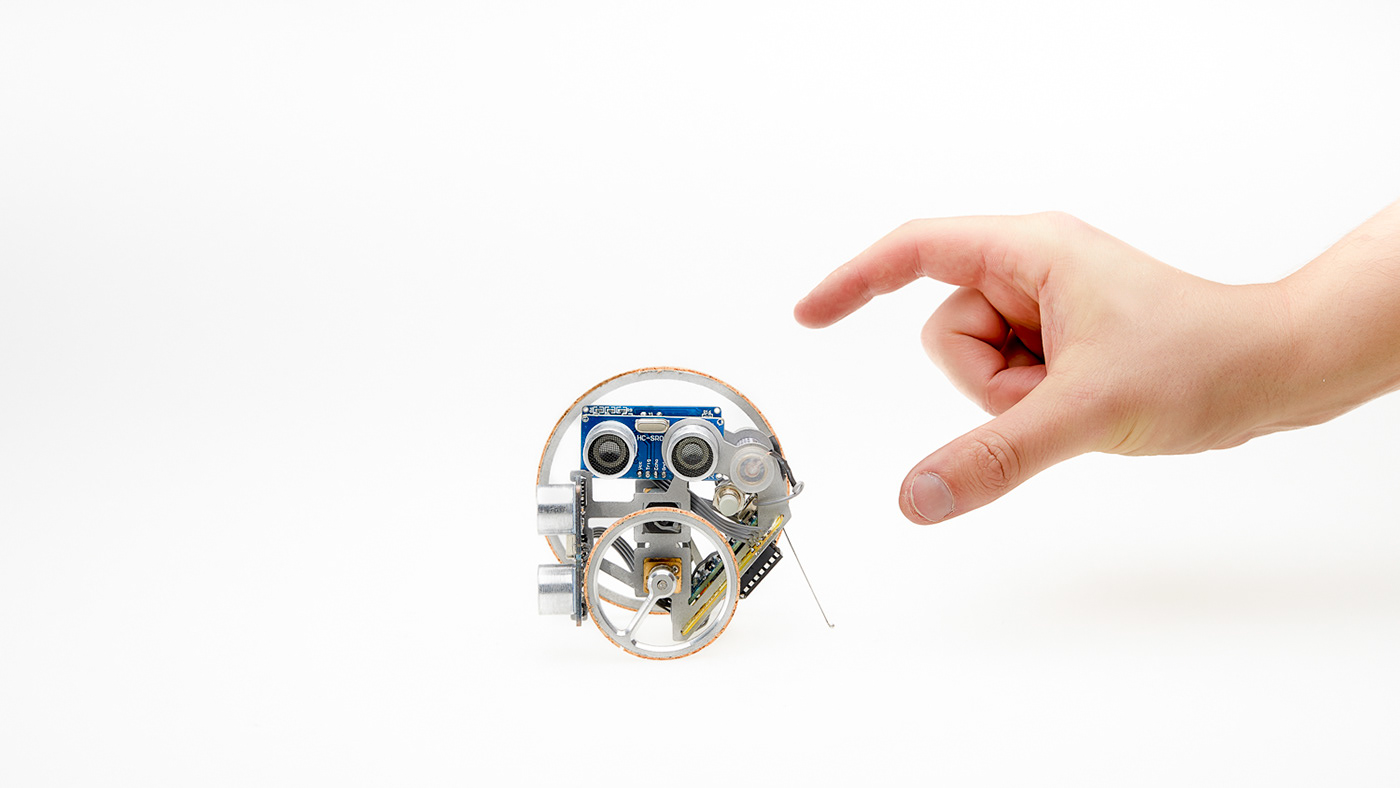
In order to keep the weight small and the dimensions compact, we decided to arrange the motors one above the other. This resulted in an asymmetrical design with wheels of different sizes. The basic frame of the vehicle consists of two cnc milled aluminium parts, which give the vehicle its stability only by joining them together with the motors and the PCB. The single-spoke wheels were also CNC milled from aluminium.
Um das Gewicht klein und die Maße kompakt zu halten, entschieden wir uns, die Motoren übereinander anzuordnen. Dies resultierte in einem asymmetrischen Aufbau mit unterschiedlich großen Rädern. Das Grundgerüst des Fahrzeuges besteht aus zwei cnc gefrästen Aluminium Teilen, welche erst durch das Zusammenfügen mit den Motoren und der Leiterplatte dem Fahrzeug seine Stabilität verleiht. Die Einspeichenräder wurden ebenfalls aus Aluminium CNC gefräst.
Result and what we learned from it
Ergebnisse und was wir daraus gelernt haben
With less than 90g our vehicle was the second lightest and could have been among the top 3 of the fastest vehicles. Unfortunately we were very unlucky in the last days before the final presentation. A finished PCB including Arduino got a short circuit and we had to quickly make another PCB. Furthermore, the 12V battery did not provide a constant voltage and therefore the different sized wheels could not be adjusted optimally and the vehicle therefore did not drive perfectly straight.
Even though we have not achieved our goal of designing the lightest and fastest vehicle, we look back on the project with a smile. I learned how to program an Arduino, how to make printed circuit boards and was asked to solve new problems every day.
From now on I will test final components much earlier with prototypes and adjust the concept if necessary.
From now on I will test final components much earlier with prototypes and adjust the concept if necessary.
We encourage everyone who is interested in technology to study Arduino and wish that all industrial design schools include Arduino courses in their teaching plan.
Unser Fahrzeug war mit unter 90g das zweit leichteste und hätte unter die top 3 der schnellsten Fahrzeuge kommen können. Leider haben wir in den letzten Tagen vor der finalen Präsentation sehr viel Pech. Eine fertige Leiterplatte samt Arduino bekam einen Kurzschluss und wir mussten schnell eine weitere Leiterplatte anfertigen. Des Weiteren sorgte die 12V Batterie nicht für konstante Spannung und somit konnten die unterschiedlich großen Räder nicht optimal eingestellt werden und das Fahrzeug fuhr daher nicht perfekt gerade aus.
Auch wenn wir unser Ziel das leichteste und schnellste Fahrzeug zu konstruieren nicht erreicht haben, blicken wir mit Freude auf das Projekt zurück. Ich habe gelernt einen Arduino zu programmieren, Leiterplatten herzustellen und wurde tagtäglich gefordert neue Probleme zu lösen.
Von nun an werde ich finale Komponenten viel früher mit Prototypen testen und ggf. das Konzept anpassen.
Von nun an werde ich finale Komponenten viel früher mit Prototypen testen und ggf. das Konzept anpassen.
Wir ermutigen Jeden, der Interesse an Technik hat sich mit Arduinos auseinander zu setzten und wünsche, dass alle Industriedesignschulen Arduino Kurse mit in Ihren Lehrplan aufzunehmen.