
Lighting and Emission in Octane for C4D
Version 1.0, Updated June 2023 using Octane 2022.1.1-R4 and C4D 2023.1.3
I. Intro
Lighting is arguably the most important thing in any 3D app. No light = no render. Lighting in an unbiased engine like Octane’s Path Tracing kernel is set up to mimic real world physics. The upside to this is that if we follow the rules of reality (or at least plausibility), we’ll get beautiful, realistic looking results without having to tweak too many settings and cheat too much. The downside is that if we don’t, all hell will break loose in the form of noise, artifacts, and other forms of frustration.
The first part of this guide explains how light works in Octane, and the second part deals with controlling noise and artifacts.
PDF
Downloads
Neon Matched Set c4d is a matched-ish set of colored neon tube light textures that have had the efficiency texture eyeballed so they put out relatively the same amount of light (and glow about the same with bloom).
I. How Light Works in Octane
All Emission Is the Same

This sounds weird since we’ve been taught since day one that there’s some massive difference between an HDRI, an area light, blackbody, an emissive texture, and blah blah blah, but the fact is, all emission (light generation) in Octane works in the exact same way, just with different defaults and settings.
Light occurs in Octane when a polygonal object has an emissive material applied to it. That’s it.
Some random piece of geometry with a material applied that contains either a Blackbody or Texture Emission node in the Emission channel emits light.
An Octane area light is a procedurally-generated geometry object that has a built-in Emission node. It operates the same way the random polygon object with an emissive material does, but has a few more controls to make placement easier, and different default settings. It can be set to use a Blackbody or Texture Emission node the same way a material can. The area light is a plane (rectangle) by default, but can be set to be a disc, a sphere, a cube, a cylinder, or a few other shapes.
An Octane targeted area light is an area light with a C4D Target tag so it can aim at an external object. This tag can be applied to any light (or object) after the fact, this is just an easy shortcut to get this tag on a new light.
An Octane IES light is an area light that has some (but unfortunately not all) defaults set to make working with IES textures easier. We’ll dive more into this later as well.
An Octane spot light is an area light that has an adjustable spotlight distribution. It uses Octane’s Spectron system to give it a few more custom controls like barn doors and a volumetric cone to help simulate a real spotlight better. We’re not going to cover this here since it’s pretty niche.
An HDRI or texture environment is a giant sphere that has an emissive texture on the inside. The power settings for this and the sun/sky rig is on a completely different scale than a smaller fixture because they’re meant to simulate an entire environment which puts out orders of magnitude more light than an LED bulb.
An Octane Daylight rig is a bundle of procedural textures and geometry that simulates a huge, powerful light source that’s super far away (or “The Sun” as we like to call it). While this operates the same as any other light behind the scenes, this rig hides and obscures a lot of the standard controls to make it more intuitive.
Emission
In the real world, anything that emits light (we’re talking the actual emitting substance itself like a filament in an incandescent bulb, the semiconductor in a LED, or a ball of burning hydrogen in space) emits in all possible directions that the emitting surface allows for. This means the rays themselves are never parallel or directable.

The closest natural thing we have to a parallel light is the sun, which still emits in all directions, but since it’s so large and so far away, we’re only receiving the tiny portion of the rays from it that are essentially parallel with one another (they have to hit our tiny rock from millions of miles away, so only the ones going in pretty much exactly the same direction get here). Lasers also emit in all directions when the light itself is generated, but they have a complicated system of redirecting the rays once they’ve been emitted that’s not currently simulated in Octane.
Octane’s Path Tracing kernel is an unbiased render engine which mimics this behavior, and therefore we can’t control or align the rays that are coming from an emitting surface.
Why This is Important
This omnidirectional emission behavior, when combined with realistic falloff (how far a ray will travel before running out of energy) and secondary bounces (Global Illumination), produces very realistic lighting without us having to dink around with too many settings like we would in a biased engine. This is great!
What’s not so great is that it’s difficult for an unbiased engine like Octane’s Path Tracing kernel to calculate the paths all of these rays, especially when some (or a lot of them) are blocked or hiding behind materials with properties like refraction. This difficulty causes calculation errors which add up and are visually represented as noise and artifacts like fireflies. If we throw enough time (samples) at the problem, we can usually end up with a decent render, but wouldn’t it be better to just set it up right in the first place to make everything as fast and efficient as possible?
What We Can Do
Octane is set up to mimic real-world physics with light and materials, so the best thing we can do is use real-world values. For this, we’re going to need to learn about how those values are translated to light and material settings. Then we can take care not to do things that are particularly hard on the engine if we don’t have to. Finally, we can make use of AI and some other tools to help optimize the sampling strategy so the render will resolve faster without compromising the beautiful look of an unbiased render. If all else fails, we can either brute force it by throwing a lot of time at it, or just flat-out cheat.
Wattage/Efficiency (Power/Texture)
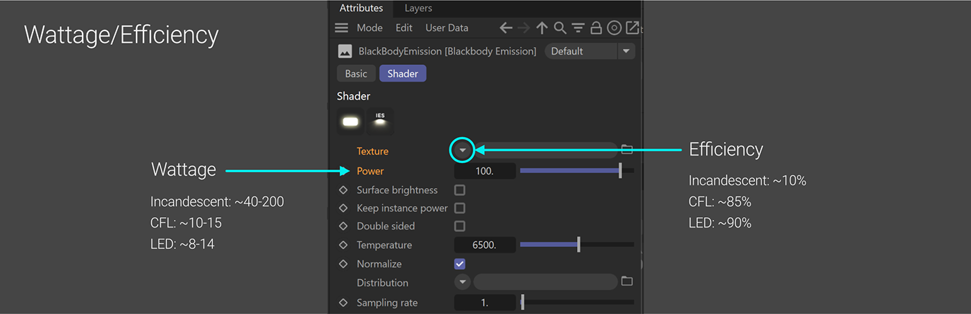
In Octane, emission works on a wattage/efficiency model.
The Power field in the Octane Light tag refers to the Wattage of the light source, so a 100 Watt incandescent bulb would be set to 100 Power, and a 12 Watt LED would be set to 12 Power. All well and good, but as anyone who has shopped for bulbs can tell you, a 12 Watt LED puts out roughly as much light as a 100 Watt Incandescent.
The difference is in efficiency.
In Octane, efficiency is determined by the Texture field. Incandescent bulbs may use 100 Watts, but they are about 10% efficient (the other 90% of the energy goes to heat). To simulate this type of bulb, we’d use 100 in the Power, but attach a texture node (like a Float Texture) to the Texture field and set it to 0.1. LEDs are about 90% efficient, so if we took the same light and set the Float Texture in the Texture field to 0.9, we could drop the Power to 11 to simulate the LED and get about the same amount of light as our incandescent light.
Important: In order to simulate real-world lights, we MUST put a texture into the Texture field. There are built-in values in the different light objects that are kind of bizarre, and not visible or controllable in their current state, so we’re going to want to override them by attaching a node to set our own values.
A Blackbody or Texture Emission node in a material defaults to a Float of 0.025 (2.5% efficiency). An area light defaults to 0.1718441 (~17.2% efficiency). This means that out of the box, if we make a Plane object and apply an emissive material to it, it will put out far less light than an equally sized Octane area light. If we manually override and set the values, we can get these two objects to behave exactly the same.
Gaussian Spectrum Texture
Octane is a spectral render engine, meaning its native way of defining light (and color) is via wavelengths, widths, and power, just like real physics. The Gaussian Spectrum node works with these values, and is what will produce the best and most realistic results.
RGB/HSV models are also supported (in the form of an RGB Spectrum node), but Octane will convert them to Gaussian before it renders. RGB/HSV can produce unrealistic colors which cause problems when trying to convert to Gaussian, so sometimes there will be blown-out or noisy harsh areas if extreme RGB values are used. The more we can use a Gaussian Spectrum texture rather than an RGB Spectrum or Float texture (especially with emission), the better off we’re going to be. We’ll cover the specifics of how to work with this node later.
Dobromir Dyankov (inlifethrill) has a fantastic (and entertaining) writeup here: https://inlifethrill.com/octane-render-rgbspectrum-vs-gaussianspectrum/
Surface Brightness

The Wattage/Efficiency model works great for real-world smaller scale light fixtures, but this means it relies on real-world scaled objects and emission sources.
For example, let’s say we built a polygon model of an incandescent lightbulb. We made it 2 3/8” in diameter (~5.9 cm) since that’s about how large it is in real life. We put an emissive material on it that has a power of 100 (100 Watt), and a Gaussian Spectrum set to 1/1/0.1 in the Texture field to reduce the efficiency to 10% like a real incandescent bulb.
With Surface Brightness OFF, this texture puts out the proper amount of light when attached to our model because it assumes that the bulb is about the correct size (which it is). Great - if we want to make a realistic interior, This Is The Way, since we can trust the values of the various light sources in our scene to put the correct amount of light relative to one another.
Now let’s say we bring our bulb into a scene that wasn’t built to scale - like ten times larger. No problem, we’ll just scale our bulb up 10x. With Surface Brightness still off, suddenly we have a miniature sun in our scene flooding it with light because the emissive surface is far too large.
This is where Surface Brightness comes into play. We’re no longer worried about matching a real world light source, and we’re just trying to get the material to look right by winging it. If we enable Surface Brightness, the emission texture now takes the size of the mesh into consideration and keeps the surface of the mesh the same brightness (ah-hah!) regardless of how large or small the object is. Our jumbo 10x sized bulb now kindasorta looks like what we might expect a novelty giant lightbulb-shaped table lamp to look like. If we scale it to 100x, it would still look about right.
If we then reduced our bulb back to real-world scale while keeping Surface Brightness on, we’d see it’s far too dim. The surface polygons are still the same brightness, but there’s not a whole lot of surface area now, so it’s not emitting a lot of light as a whole - we’d have to compensate with more power (or turn surface brightness off).
So in a nutshell, if we’re going for accuracy and matching a real light that we have the specs for, we want to keep surface brightness off and put in the correct power (Wattage) and efficiency (Texture). If we just want some arbitrary glowy thing in a scene (especially one that animates in size), or if we’re using neon tubes or something that can be lots of different sizes but need to keep the same apparent brightness, we’ll want surface brightness on, and just eyeball the power until it looks right.
By default, it’s on in an area light and off in an emissive texture.
Distribution
If we’re looking for realism, visual interest, or better render times with our interior lights, the Distribution field is where the magic happens.

The projection of a Blackbody or Texture Emission node is always Spherical. That means light goes out from all possible directions from the normal side (front) of the polygons, just like in real life.
Now, in real life, this emissive element would be contained in a glass or plastic bulb which is then set into in some sort of housing. The bulb itself may diffuse or refract some of the light, and the housing would block some of it, and possibly reflect or refract some of it depending on the type of fixture.
If we were to simulate this exactly in an unbiased engine like Octane by building out a fixture that blocks some of the light and focuses or diffuses other parts, the difficulty of calculating all those rays would go way up (especially with a lot of refraction), and we’d end up with a horrid mess of fireflies and noise that would take a ton of samples and time to resolve (if ever) due to the nature of path tracing.
Even if we were able to get the noise under control, we’d have to keep tweaking the lens, glass shape, housing shape, etc. etc. to get a close approximation of how the light is actually distributed. We’ll get more into noise and artifacts later, but if we’ve spent any time messing with lights, we know these perils well.
Fortunately, the Distribution field allows us to simulate what real world lights do in their housings by blocking or dimming portions of the emission texture itself. We can apply a texture to the surface meant to emit light (instead of burying it in a glass tube), and the material simply won’t emit rays from these problematic places and dim the portions that would normally be semi-blocked, and we’ll end up with an approximation of how the light would really function in its enclosure in a much shorter period of time.
Obviously this wouldn’t be great if our render was a macro shot of a lightbulb, but it’s very convincing in interiors and other scenes where we’re not hyperfocused on the emitting element itself.
Distribution Textures
As mentioned, the Distribution field takes a texture. We could put some random texture in there like a noise or checkerboard or something and get interesting results, but since all light in Octane is spherical mapped, it’s hard to control. So let’s look at two ways we can acquire or make good distribution textures.
Spotlight distribution
A quick and easy way to see what Distribution actually does is with a special texture that comes with Octane called a Spotlight Distribution node.

The spot distro effectively takes the full spherically mapped emission area of the material and blocks out most of it, leaving a small circle on one side that produces a directional cone of light. The larger the circle, the less of an area it blocks and the wider the cone gets. The fuzzier the edges of the circle, the softer the spotlight becomes.
Important: If we’re using this in an emissive material on random geometry, we need to set the Orientation to “Direction - object” space so that when we rotate the object, the spot goes with it. There are other options in here too, like Direction- world space if we want the light to always point down, for instance. This is only an issue with an emissive material - Area lights with the default spot distro will aim correctly.
Because we’re blocking part of the emitting texture, the smaller we make the cone, the less light is emitted, and if we make it too small, we may not see anything until we crank the power. Just something to be aware of.
IES Lights

The IES (Illuminating Engineering Society) developed an open standard for these types of textures which is accurate enough to use in engineering light simulation programs such as Dialux, but also great for artistic 3D engines like Octane. In fact, the .ies file itself can be used directly in Octane without conversion.
IES files are available on most light manufacturer’s websites for free, since they want you to simulate their lights and eventually buy the real ones for your home or commercial space. Even better, 3D models of the actual fixtures are also usually available for free from the same locations, so we can map our real distributions to real looking fixtures! Also, the IES data handles efficiency for us, so no need to guess at that or spend time researching.
Proper IES Light Setup
Because .ies files are engineering data, and not an artistic image texture, there are a few things we’ll need to do to set up an IES light correctly if we’re trying to match the real-world data contained in the file. We can use IES files in either an Octane Light object like the Area Light, or in an emissive material. Both are essentially the same, but have different defaults and considerations.

If we’re using an Area Light, we need to scale the light to about the size of the fixture the IES data was designed for. This is in the actual light object’s (not the tag’s) Details tab.
If we’re using a material, all channels except for Emission and Opacity should be set to pure black and/or 0 float (no contribution) - this especially important for the Albedo/Diffuse channel. Opacity should be set to 1. It’s usually easiest to use a Diffuse material for an emissive since there are fewer things to turn off. We then need to hook up a Blackbody Emission (not a Texture Emission) to the Emission channel, and turn OFF surface brightness.
The rest of the steps are the same for both a light and an emissive material.
The Emission’s Power and Temperature should be set to the real-world power and temperature of the light the IES data is based off. If we can’t find the specs on the manufacturer’s site, we can pretty safely assume LED at this point which is probably somewhere in the 7.5-15W range, and the temp is probably 2800 - 7000 K
In the Texture field:
Attach a Gaussian Spectrum node and set all three values (wavelength, width, power) to 1. The IES texture will handle the efficiency for us, but intentional dimming can be done by reducing the Gaussian Spectrum’s Power.
In the Distribution field:
· We need to remember to ALWAYS. USE. AN. IMAGE. TEXTURE. NODE! If we just click the little down arrow next to the Distribution field and choose the IES file instead of c4doctane>ImageTexture, the IES will import in a C4D Bitmap shader, and this will wreck everything. There will be wailing, gnashing of teeth, fire and brimstone unless an Image Texture node is used.
· We need to make sure to load the .ies file in the File field and not the .png preview that’s sometimes included.
· The ImageTexture’s Power should be set to 1 - we’ll adjust the dimming in the Gaussian Spectrum node.
· The ImageTexture’s Color space should be set to non-color data. Gamma then doesn’t matter.
· The ImageTexture should have a Projection node attached, set to Spherical - this will allow us to aim the light, where UVW Projection will not (even though the emission will still be spherical).
Coloring lights
In Octane, we have two different methods of coloring lights. The Blackbody Emission node uses the scientific black body radiation scale often used in real world light fixtures or to describe celestial objects like stars. This is ideal if we’re trying to simulate an interior light fixture (like an IES light), or just to make a warmer or cooler light. For neon or other lights that use colored glass or gels, we can use the Texture Emission to choose a color that’s not on the black body scale.
The only difference between Blackbody and Texture emission is how the coloring is handled.
Blackbody Emission

Texture Emission
The other way to color light is via the Texture Emission node. This relies on the (wait for it) Texture input to specify the color, rather than have a separate temperature control like Blackbody. If we remember, though, the Texture field is there to control efficiency, so there’s now a relationship between the color and efficiency (which is how it works in the real world also). Different wavelengths have different apparent brightness.
We can put any texture we want in here, but if we’re after a particular color, our options here are an RGB Spectrum node for defining the color via RGB or HSV, a Float Texture to get a 0-1 grayscale, or a Gaussian Spectrum which is really what we want to best control noise and fireflies.
If we use RGB or Float, we want to avoid extremes like 255,0,0 (or 1,0,0 if we’re using Octane’s color model), or float higher than 0.95 or so. All Gaussian values are real-world, so we won’t run into any trouble there.
To control the color with a Gaussian Spectrum node, we have to work in small increments and kind of treat it sort of like an HSV color model. It gets tricky because of how light works and the eye interprets it. The three values in the Gaussian Spectrum node (wavelength, width, and power) are all interdependent, and it’s not just a simple matter of moving one slider to get the right color.
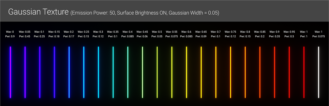
Wavelength is kindasorta like Hue. In the real world, the visible light spectrum’s wavelength range is 380-720nm, but in Octane it’s been remapped to a 0-1 scale with 0 being violet and 1 being red.
Width is kindasorta like Saturation, but what it’s really doing is spreading out the range using the Wavelength value as a central point, so the color starts to blend in with adjacent colors and less saturated-ish as it gets larger. A width of 1 gives full spectrum (white) light like the bar on the far right in the illustration above. A width of 0.05 gives a very narrow band which isolates single colors a lot better, like all the other bars above.
Power is kindasorta of like Value, but it also relies heavily on the color. In the illustration above, we can see that with the same Emission Power and same width (except for white), we need to drop the Gaussian’s Power all the way down to 0.05 for the 0.5 wavelength tube (greenish yellow) to get to about the same relative intensity as the 1 wavelength tube (red). It kind of operates on a bell curve, and can be tested by cranking the Bloom post effect and seeing if one particular color is a lot hotter than another.
II. Noise, Fireflies, and Heartache
The Problem
An unbiased path tracing engine like the PT kernel in Octane works by firing out a bunch of rays into the scene from the camera and then calculating their paths back to all the various light sources.
The more difficult the paths are to resolve for each ray, the more calculations (samples) the engine will need to get a clean result. This difficulty is visually represented to us in the form of noise and artifacts.
These calculations were designed to mimic reality, so unrealistic values in the lights and materials are more difficult to resolve, and end up causing more noise, or - when the values get really extreme and the calculations start to break down - visible render errors which appear to us as artifacts like fireflies, color clipping, and hotspots.
This isn’t to say that a perfectly realistic scene will resolve clean and quick every time. If the paths to the light sources are obscured, blocked, or redirected (like through refractive glass), the calculations become MUCH harder and take longer to resolve cleanly.
How We Can Help
Our first job is to help the engine help us by not adding to the problem and making sure we’re using realistic values for everything. Once we do all we can to optimize our scene, our second job is to use tweaks and cheats to clean up the rest of the render to get an acceptable result.

Real-world Scale
First and foremost, we always want to make sure our scene is real-world scale. The quickest way to test this is to drop a standard C4D Figure object into the scene. This will tell us straight away if our houseplants are the size of a fingernail, or our chair is meant for giants. We want to get get all our objects as close to the size they’d be in real life as possible so that the light interacts with them properly. If our objects are abstract like sculptures, we want to make sure they’re within reason too - as a species, we rarely build a 200 meter high statue (and if we do, we certainly can’t light it with a few neon tubes). Plausibility is key.
If we’re using real light fixture geometry downloaded from a manufacturer’s site, we want to make sure that’s also scaled properly. Sometimes these will import in millimeter scale instead of centimeter, so they’ll have to be adjusted accordingly when brought into C4D.
Check the Normals
A lot of these calcs rely on good normals in the geometry, especially with emitting surfaces, so we’ll want to make sure as many as possible are facing outward (orange in C4D, not blue when selected). This can be particularly bad with imported CAD models.
Realistic Materials
Our materials should also be physically plausible. If we’re using RGB Spectrum for our colors in the Albedo/Diffuse channel, we want to make sure we don’t go too extreme (not having anything that’s 100 red and 0 percent green and blue, for example, or avoiding 100% S or V values if we’re using an HSV model). If we’re using a Gaussian Spectrum, we don’t have to worry about this, but it’s a bigger pain to find an exact color this way.
Aside from RGB spectrum colors, the next biggest offenders are usually IOR and Dispersion. The more unrealistic those are, the worse the render errs will be. Displacement and Mediums are particularly hard to calculate, so if they can be avoided and replaced with fakes like Bump and Diffuse Transmission, that’d speed things up. If not, they just need to be optimized and kept within the realm of reality.
Lights
Just as a quick recap: We’ll want to put a texture of some sort into the Texture field to control the efficiency manually. The Gaussian Spectrum node is our best bet most of the time unless we need an exact color that we have RGB values for. If we’re using an IES distribution, it will handle the efficiency for us, so we can just use a Gaussian Spectrum set to 1/1/1, and then lower the Power for intentional dimming (like if the light is on a dimmer switch).
Placement & Blocking
A hard and fast rule that we need firmly implanted in our heads is that we want to avoid blocking or obscuring as many light rays as possible - especially the most powerful ones. Instead, we want to mask and control the distribution and move our fixtures around so they’re emitting outward and as unobstructed as possible.

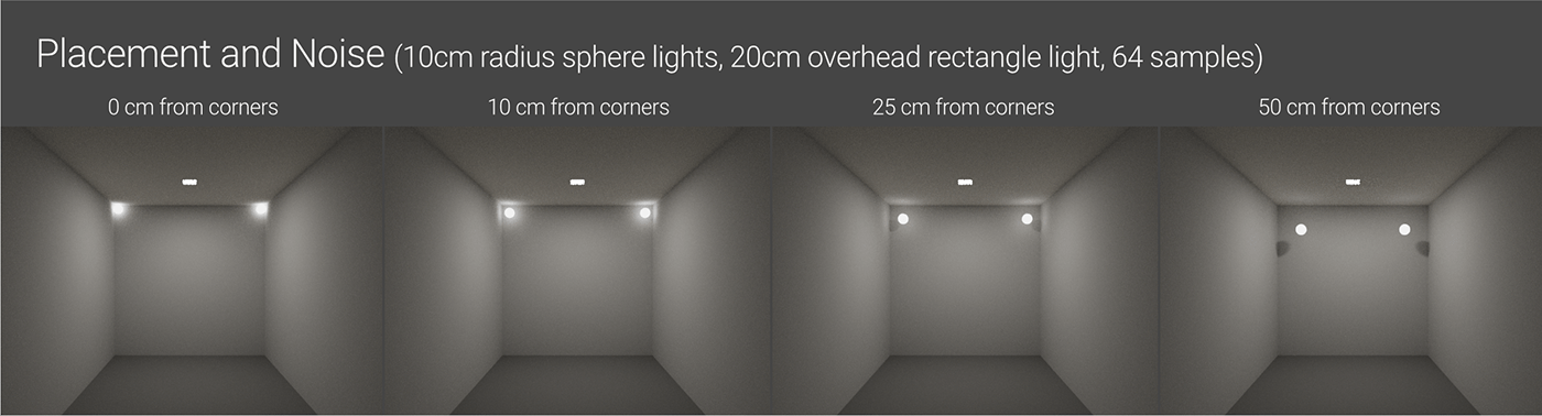
In the scene above, the lights and environment are exactly the same. We’re seeing two omnidirectional 10cm radius area light spheres with a Power of 10, Gaussian Spectrum Texture 1/1/0.2, “Use primitives” is on, and there’s no distribution texture. Render settings are Pathtracing, 64 samples, AI Light on, all others at default. The only difference is how far away the lights are from the walls and ceiling.
These are the only two lights in the scene, so all the rays used to illuminate the scene must trace back to them. The more obscured some of the emitting area is, the harder it is to calculate and the more noise appears.
This is the same scene, but the sphere lights have been dimmed way back to 1 power, and an overhead rectangle area light was added as our main source of illumination. Power for the overhead is at 20, Texture is Gaussian 1/1/1. It’s placed 1cm off the ceiling. The ceiling light is still spraying rays in all directions, but ONLY from the bottom side, so none of them are blocked. It’s the most powerful light source in the room, so most of the rays will trace back to it, and even with the other two less powerful lights snugged against the walls, the scene is not very noisy at all at 64 samples. The same strategy can be used with distribution textures, even if a light is recessed, to make sure rays aren’t being blocked.
AI, Tweaks and Cheats
If we’ve done all we can do with the geometry, materials, and lights, there are several options in the render settings that were built to help with noise and artifacts. They all have varying levels of success depending on the scene.
AI Light System & Spectron
The relatively new AI Light system uses algorithms to learn each individual scene and optimize sampling for it. Practically this means that the number of samples it takes to resolve a clean render goes way down if this is on. The great part about this is that this system is still unbiased, meaning we still get beautiful natural looking light. It’s not limiting rays, it’s just prioritizing how much attention to put on particular ones to resolve them cleaner. This affects all emission in Octane, so most of the time it’s best to have it on unless it’s causing issues in a particular scene.
There’s a checkbox in the Kernel settings that says “AI Light”. All we need to do is tick this and we’re good to go.
Spectron is a procedural lighting system that’s native to the Octane Render Engine that simulates even more realistic lighting. It has a whole host of features that we’re not going to dive into in this guide. Instead, we’re just going to concentrate on Spectron Primitives which make Area Lights a lot faster and cleaner, especially when combined with the AI Light system.
As of this writing, Spectron is only available in Area Lights, so back when we said all emission is exactly the same, we may not have been 100% honest :/

In the Octane Light Tag (in the Light Settings Tab) there’s an option for “Use primitives” - this replaces the area light with a Spectron Primitive. In the Light Object’s settings (not the tag), in the Details tab, there’s a dropdown for Area Shape. This allows us to choose a shape.
Important: Currently only the Rectangle (a plane, essentially), and the Sphere are supported by Spectron and will be swapped out with corresponding Spectron versions. The other primitives here (Disc, Cylinder, etc) will still change the shape of the light, and still benefit from the AI Light optimizations, but they won’t be replaced by Spectron primitives.
The Outer Radius, Size X and Size Y values will change the size of the light. Everything else in this section is for C4D’s native engines only and will be ignored by Octane.

The illustration above shows off the difference between a regular spherical piece of geometry with an emissive material, an Area Light set to Sphere (without Spectron), and an Area Light set to Sphere with Use Primitives (Spectron) enabled. It also shows how these options interact with the AI Light system.
In all cases, the spheres are 20cm in diameter, there’s a Gaussian Spectrum node controlling the Texture set to 1/1/0.2, the temperature is at 4000 K, and the Emission Power is set to 7.5. The room is a fully enclosed box with no other lighting, and different materials for the ceiling, walls, and floor to help show off the noise in both darker and lighter areas. GI Clamp is set to the default of 1,000,000, and no denoising or hotpixel removal was used.
As we can see, there isn’t much difference when we’re using a non-Spectron Area Light and a piece of geometry with an emissive material. The AI Light system does a great job with either. When Spectron Primitives are enabled, the scene gets cleaner even without AI Light on, and then much cleaner with.
This does means we have a decision to make if we’re using real-world fixture geometry downloaded from a light manufacturer’s site. We can still use an emissive material with the proper distribution texture on the emitting portion of the fixture, turn AI Light on, and deal with any noise in another way. The other option is that we can create a sphere or rectangle Spectron area light, bury it in the fixture, and use Light Linking to hide the fixture from the area light. A different material would then have to go on the “emitting” portion of the geometry with a very low powered emission that doesn’t affect the light in the room. We’d probably only go to this extreme if we have a very tricky lighting situation and couldn’t control the noise in any other way.
Adaptive Sampling
Adaptive sampling still maintains the unbiased, realistic look of the render, it just prioritizes how the sampling is distributed in scenes where some of the frame is super easy to render and other parts are very difficult. It works by building a noise map (which we can actually see in the Live Viewer at the bottom). When a particular portion of the render is deemed “clean”, Octane stops refining it with more samples and focuses its attention on the noisier sections.
This has mixed results, depending on the complexity of the lighting in the scene and rendering difficulty. Sometimes it’s great and will help clean up problematic areas faster. Sometimes it can actually introduce fireflies and other render areas if the scene is a lot simpler and doesn’t need as many samples. There are settings to adjust the threshold and minimum samples to tweak it even more.
Adaptive Sampling is also unbiased and works really well with the AI Light system.
Path Termination (Path Term) Power
If we find ourselves with a scene where the noise in dark areas is particularly bad regardless of everything else we try, we can lower the Path Term which will cause Octane to spend more time resolving the darker areas. This will increase render time, but may fix this issue. Alternatively if we don’t have many dark areas, we can experiment with pushing it the other way to a higher value and see if we get a boost in speed. Most of the time we can clean our scene up without this, though.
GI Clamp
GI Clamp is the more traditional way to keep noise down, but takes our lovely unbiased render and starts to add bias to it. This setting limits secondary bounces in the scene (and the noise that causes), but it detracts from realism as it gets lowered more and more in scenes where secondary bounces are what give it that magic look (like interiors).
Fortunately it doesn’t need to be lowered as aggressively - or even at all - if we’ve done our jobs well in the prior section and kept everything realistic and unobscured as possible, since many of the problematic light rays would end up naturally going extinct anyway before they caused issues. We also now have better options with AI Light and Adaptive Sampling, so this should really be used as a last resort, of if Global Illumination is just not a concern (like in a very graphic, non-photoreal look).
Important: Using GI Clamp with AI Light can mess with the render, so if we want to use the AI Light system, it’s best to pick one or the other. If we go with AI Light, we’ll want to keep the GI Clamp at default (a million).
Hotpixel Removal
This is a post-processing effect that is designed to target fireflies. The default is 1, and as we drag it down, it lowers the threshold for super bright pixels in the render and removes them. It works great if there’s a lot of contrast in the scene and the fireflies are glaringly obvious, but if it gets set too low, it can start removing some of the highlight detail from the render. Usually around 0.5 is good for this.
Denoiser
This uses AI to denoise a scene. This can drastically reduce the render time of a scene (we’d only need, say, 128 samples to get a clean result rather than 4096), but depending on the scene, it can introduce a particular overly-processed look or wreck tight-knit patterns or introduce artifacts into animation. It should be thought of as more of a polishing pass than anything else for most scenes.
Light Linking
If all else fails, we can use Light Linking to tell a very problematic light source not to interact with a very problematic object. Obviously we can’t do this in real life, so it’ll decrease the plausibility of our scene. We may also then have to revisit other lights and fiddling with them to compensate.
In recent versions of Octane, we’re now able to use C4D’s Light Linking system where we can just go to the Project tab of a light (the light object itself, not the Octane tag) and drop in objects we don’t want it to affect.
C4D Light Linking needs to be enabled in the Octane Render kernel settings if we want to work this way.
Wrap-up
That about covers most of the important stuff that relates to lighting in Octane. Hopefully this guide gave you a better understanding of how it all works and will help you produce faster, cleaner, more realistic renders.
Reference
Writeup of Gaussian vs RGB Spectrum: https://inlifethrill.com/octane-render-rgbspectrum-vs-gaussianspectrum/
Hundreds of thousands of real IES Textures for free: https://ieslibrary.com/en/home
Leomoon Studios has an excellent starter set of free IES textures
Make your own IES Textures for free: https://cndl.io
Download from this guide: Neon Matched Set c4d file
Author Notes
OG023 Lighting and Emission, version 1.0, Last modified June 2023.
This guide originally appeared on https://be.net/scottbenson and https://help.otoy.com/hc/en-us/articles/212549326-OctaneRender-for-CINEMA-4D-Cheatsheet
All rights reserved.
The written guide may be distributed freely and can be used for personal or professional training, but not modified or sold. The assets distributed within this guide are either generated specifically for this guide and released as cc0, or sourced from cc0 sites, so they may be used for any reason, personal or commercial.


