

Mograph in Octane Render / Cinema 4D:
Billiard Ball Project Walkthrough
Billiard Ball Project Walkthrough
Estimated time to follow the guide and understand everything: 1-2 hours.
Estimated time to put this rig together once you understand it all: 15-20 minutes.
About this guide
Ah yes, billiard balls. For as long as 3D has existed, this has been one of the mainstays to the point of cliché. And yet, it's the perfect project to explain how Octane interacts with the mograph color shader and multishader, as well as discuss many of the pitfalls and gotchas with effectors and color spaces. The techniques found here can be used for a lot of things, including all those corporate freelance projects that you get where you need to map 200 logos onto cubes and make them all dance around.
This guide will use Octane’s Node system for the material, mainly because it’s just a better way to work with materials. If you need a refresher on that, you can check out this guide.
Assets
This project uses some textures for the numbers and a couple of masks. They can all be found here along with a starter file and the end state of this project. Also included in the assets pack is the 4K Neon Photo Studio HDRI by Sergej Majboroda from Polyhaven. Don’t know how to use an HDRI in Octane? We got you covered. Scroll down to the HDRI Workflow section of this guide.

Setting up the scene
Initial Setup (the easy part)
If you want to skip the initial setup and go right to the Step Effector section, you can just grab the starter file along with the rest of the assets and use that. It has the initial cloner, camera and environments set up already.
Lights, Camera... Settings!
Let’s drop in an HDRI Environment and put the 4k version of Photo Studio HDRI in the ImageTexture node. To make the scene more minimal, we can also create a Texture Environment, change it to a darkish gray, and set the Type to Visible Environment. Now we’ll get lighting on the balls from the HDRI environment, but the background will be the dark gray from the Texture environment.
Let’s drop in an Octane Camera and set the focal length to 120mm in the Camera’s Object tab and get a nice high angle so we can see all the balls laid out.
As for the settings, we’re really only going to need Direct Lighting and 128 or 256 samples depending on your system. We’re more worried about iteration speed than anything at this point.
Geometry
Like many great 3D stories, this one starts with a sphere. Let’s drop one in and rename it to Billiard Ball. We’re going to use real-world scale here because given the choice, it’s always best to do so. How large is a billiard ball?
If we have a look at a reference site, we can see it’s 57.15mm in diameter. let’s call it 57mm. C4D measures a sphere in terms of radius, so let’s halve the diameter (radius=diameter/2) to get 28.5 cm. While we’re here, let’s give it 200 segments so it’s nice and smooth.
Next up let’s make a cloner, rename it Billiard Ball Cloner and drop the Billiard Ball sphere in. At first, we’ll just set them up in a grid, but after we get them looking like billiard balls, we’ll explore one non-codey way to put them in a rack in a custom pattern. For now though, we need 16 balls (15 numbered ones and a cue ball), so let’s do 4 clones on X, 1 on Y, 4 on Z to make a top-down grid. As for the spacing, let’s make it 60x1x60.
Step Effector
C4D’s default Display Color for new geometry is a middle gray.
When that object is placed in a cloner, the clones are assigned a new Display Color by the cloner (white by default). What we want is for each ball to have a unique Display Color so we can apply unique textures to each one.

The easiest way to accomplish this is to select the cloner and add a Step effector.
Note that the Step effector has its own limitations when it comes to gradient remapping, but for something like this where we have exactly the same amount of clones as textures, it’s easy, and it works.
In the effector’s Parameter tab, let’s uncheck Scale (all the balls should be the same size), and set the Color Mode to Effector Color. This will tell the clones to take their color from the effector rather than the cloner.
Let’s also uncheck Use Alpha/Strength so no other effectors interfere with it.
We’ll notice that in the viewport, the balls all change to different grays, but in the Octane Live Viewer, the balls are still white. Octane doesn’t recognize Display Color by default - we’ll need to send that data over in the material to fix that.
The Octane Part
Time to get the color data into an Octane material.
Strategy and Planning
It’s a good idea to plan ahead if a material has mixing or masking, especially a few layers of it like what we’re going to do here. This can be written out in a document “Need 16 billiard balls, nine are solid, seven are striped...”, or drawn out quickly in a 2D app to help visualize the mixing and masking and think about what assets you need to build.

Universal Material
We’re going to go with a Universal Material rather than a Mix/Layered/Composite material so we can focus on getting and manipulating Mograph colors rather than getting sidetracked with the intricacies of layering systems.
Let’s make a new Universal Material, name it Billiard Balls in its Basic tab, and go ahead and put the material on the cloner.
All of the balls in the viewport change to white, since they’re showing the material’s Albedo color (white-ish by default). This isn’t affecting or overriding their Display Color, it’s just the default behavior for what C4D chooses to show in the viewport. The balls in the Octane Live Viewer are also all white, but now it’s because they’re grabbing their color from the material.
Let’s get the node editor open and get to work.
Mograph Color Shader
In order to see the Display Color assigned by an Effector or Field in Octane, we need to use a Mograph Color Shader, so let’s find Mg color shader on the left and drag it in. This is toward the bottom of the list, and is a black node, meaning it’s C4D-native.

If we hook it up to the Albedo channel, we’ll see all the grays in the Live Viewer. Exciting.
We’re not seeing any change in the viewport though - all the clones are still white. There’s a limited amount of two-way communication between an Octane material and the viewport. It can pull a simple color or pattern from the material, but it can’t pull complex per-clone data using something like the mograph color shader. Since nothing we do is going to update in the viewport properly going forward, we may as well see the gray Display Color the step effector gave each clone. For that, we need to select the Cloner, and under Display Color choose Custom.
Remapping the Colors
Here’s where things start to get interesting. Let’s drag out an Octane Gradient. This is the magenta mapping node that says “Octane gradient”, not the black C4D Gradient, not the blue OSL gradient, not the blue Gradient generator.

If we drag it onto the wire between the color shader and the material node, it will slot in there and rewire the chain up for us. Nothing changes though. The gradient by default is black on one side and white on the other. Since we’re only feeding grayscale values in, this acts as a passthrough. Anything that was originally black gets mapped to black. Anything that was originally white gets mapped to white. Anything originally 14.928503% gray gets mapped to 14.928503% gray.

So let’s set the gradient up to give us specific colors. There are 16 balls, so we want 16 knots in the gradient, one for each ball. Currently we have two knots. Let’s right-click in the gradient area somewhere and choose “double knots”. Now we have four. Let’s do this again to get eight, and then one more time to get sixteen. If we right click in the gradient area one more time, we can choose “Distribute evenly”.
What we were expecting was that every clone would alternate between black and white. What we got was a smattering of seemingly random gray balls.

What happened?
Linear Color Space
Yes, this again, and it won’t be the last time. This is an issue that keeps coming up, and doesn’t have an easy solve because of the difference in the way our eyes see color vs how a computer processes it.
The Step Effector mathematically divides the gray values up into an even scale when it applies them to clones. Clone 0 is given a Value of 0% (black). Clone 1 is given a value of 6.6667%, Clone 2 adds 6.6667% to the prior value to give us 13.3334%, Clone 3 adds another 6.6667% to the prior value to get to 20%... until it hits clone 15 which has a value of 100% (white) That’s a linear distribution, and that’s not the problem.
The Octane Gradient is a remapping tool, and it also works on a linear scale from 0 to 1 (or 0% to 100%). So that’s not the problem either.
It turns out that the Mograph Color Shader itself is influenced by the document’s Input Color Profile, which is set to sRGB by default. The sRGB Color Profile doesn’t produce a linear black to white gradient, it operates on a curve (gamma). This more closely follows how the eye perceives color (and how screens display it), but it wreaks havoc when trying to use it to map evenly distributed things like what we’re trying to do.
Now we’re not here for a color science lesson, so at this moment we don’t really need to know why this is an issue as much as we need to know how to fix it.

What we want to do is go into the Project Settings in C4D’s main Edit menu (or use the Ctl-D or Cmd-D shortcut, but make sure you close the node editor first), and the at the bottom of the Project tab in the Attributes Manager, in the Color Management section, change the Input Color Profile from sRGB to Linear. The “Linear workflow” checkbox should be ticked by default, but if not, let’s make sure that’s on too.
Suddenly this all works properly now - every other ball is black or white, because everything’s mapped in a linear fashion.
Setting up the Octane Gradient
Now that we’re confident that we have a predictable linear gradient so we can control the color of each clone, let’s pop the node editor back open, select the Octane Gradient, and get our final colors in. An app like PureRef (free) can come in handy here to keep the palette in a small window on top of C4D. Otherwise we can just split-screen the apps or type the values in manually.

An easy way to do this is to use the eyedropper to sample the colors. We can do that right from the illustration above. In fact, to make our lives even easier, we can delete half of the knots, put the cue ball color in the first knot, then the 1 ball yellow, 2 ball blue, etc until we get up to the seven ball. Once that’s done, we can right click in the gradient area, select “double knots” which will duplicate all the colors we have, and then choose the second cue ball color knot and make it black for the 8-ball. Now we can click in the gradient area one more time and choose “distribute knots” again, and voila - we’ve got what we want.
If we want to see what kind of mess we were in for before going Linear, we could hit control/command-d again (outside the node editor), and set it back to sRGB. Ew. Ok, back to Linear.
Mixing and Masking
Excellent - all our balls are colored appropriately. Time to dress them up. The main reason we gave the clones unique gray values was so we could use the Mograph Color Shader to determine which clones get which color. A secondary use for it, though, is to determine which clones get other utility effects like masks or even different projections.
Our node graph is going to get somewhat complex going forward. In cases like this, it’s always a good idea to keep as organized as possible through good layout and proper naming.
Speaking of proper naming, we can actually rename the nodes too, which is going to be very helpful here in keeping our own sanity in check, as well as anyone else’s who sees the file. We’ll be using a bunch of gradients and mix texture nodes, so we want to know at a glance what does what.
Setting up the Stripe Mask

The first mask we’re going to use Stripe Mask.png included in the assets. Let’s make a new ImageTexture node, load that image in, and connect it right up to the albedo channel. Bunch of eyeballs, great. Let’s reorient the clones. In the cloner’s Transform tab, we just need to set the R.P value to -90 so all the balls are facing us.
Even though there’s a thumbnail here, we still want to rename the ImageTexture node in case we want to collapse it later. Let’s call it Stripe Mask.
While we’re thinking about it, let’s also click our Octane Gradient, and in the Basic tab on the left, call it Ball Colorizer.
Determining Which Balls Are Striped
All of our balls are striped now, but in a traditional billiards set, only seven of the balls are (9, 10, 11, 12, 13, 14, 15). How can we pick which ones we want?

We’re going to use another Octane Gradient to remap them to either black or white. For now, let’s disconnect the Stripe Mask Image Texture from the Albedo channel and set it aside.
The cool part here is that we can use the same Mograph Color Shader to drive this gradient as we used to drive the colorizer one, so let’s hook our Mograph Color Shader up to the Albedo channel and bring a new Octane Gradient node in and drop it on that wire so it goes between the Color Shader and the Albedo channel.
We want the first nine clones to be black (solids), and the last seven to be white (stripes), so if we move both knots to around 56% or so we can see in the Live Viewer that this gives us pretty much what we want.

If we’re super accurate about it and get the knots right on top of one another, we can probably get the masking exact, but if we were moving fast, or had a lot more knots that we had to be crazy precise about, odds are really good that it’s going to be a little off and produce a very light or very dark gray instead of a white or black. This will cause the textures to blend a little and there will be some weird ghosting effects. Wouldn’t it be nicer if we only had one knot to worry about so that we could position exactly where we want?
Octane vs C4D Interpolation
Cinema 4D has a mode called Step for the gradient knots that removes the interpolation between knots, so either it’ll be black or white - no other grays will even be possible. Let’s right-click in the gradient area somewhere and choose “Step” under Interpolation of all knots. Now we can move the knots all we want, and it’ll make a hard gradient between the knots and divide our balls into either black or white.
Or will it?

If we move both of the knots around, we’ll see... grays. Why? Turns out, Octane doesn’t respect the interpolation settings of the C4D gradient knots.

The silver lining is that the Octane Gradient node DOES have its own interpolation settings, and those are in the often-overlooked Interpolation dropdown above the Texture area. If we set that from Linear to Constant, we’ll get what we’re after. Most of the balls are now 100% black, and the ones on the right are 100% white. Now If we drag the white knot around, we’ll see the distribution change.
Important note here: The Octane interpolation overrides the Cinema 4D knot interpolation in the Live Viewer and Render.
In other words, if we were to leave the Octane Interpolation at Constant and change back the C4D knot interpolation to Smooth, we’ll see that it still acts like a step gradient, even though visually we’re seeing a smooth blend. This can get really confusing, so let’s make sure the Octane interpolation is on Constant AND the C4D one is on Step.
Finally, let’s make sure the black knot is all the way to the left and drag the white knot until only the last 7 balls are white. Perfect, we can now use this in our mix.
First Mix Node - Applying Stripes to Seven Balls
There are actually several ways to mix and layer textures and materials, many of which can be found in the Material Mixing & Layering guide. We’re going to try to keep this as straightforward as possible in this guide, so we’re going to use Mix Texture nodes for all our mixing needs. Let’s drag out a Mix Texture node and name it Solid/Stripe Mix.
This has three inputs - Texture 1, Texture 2, and Amount.

The Amount input is the one that determines which clone gets how much of each texture.
Let’s feed our Solid or Stripe gradient into the Amount input of the Solid/Stripe Mix.
Now we have to determine which texture goes in which slot.
Texture 1 is going to be our “unaltered” clones - our solids - represented by black in our Solid or Stripe gradient.
Texture 2 will be our “altered” clones - the ones that get the stripe mask - represented by white in our Solid or Stripe gradient.
Texture 2 is easy enough, we just want the Stripe mask to go on the white balls, so let’s feed that into the Texture2 slot in the Solid/Stripe Mix node.
We need to think about Texture 1 more carefully, though. What color should that be? If we look at the stripe mask, the white area is going to eventually get colors from our colorizer gradient, and the black area will get that off-white bone color of the cue ball. Since our solids are going to be all the color from the colorizer gradient, it would make sense that for masking purposes, those need to be solid white as well.
So we want to build a white texture for our solids. We can either do this with an RGB Spectrum node, or, since we’re building a mask and are only thinking in terms of a 0-1 grayscale, we can drag out a FloatTexture node and set it to 1. This represents pure white on the float’s 0-1 scale, and isn’t affected by gamma curves or anything. Let’s run that into the Solid/Stripe Mix’s Texture1 slot.
Second Mix - Adding Color Back In
So now all our balls are set up to determine where the Ball Colorizer colors will go, but we need a node that just spits out the bone color from the cue ball so we can put that into the areas that are currently black.
This time around we’ll use the RGB spectrum node rather than the Float Texture node, since this will be a precise RGB color we want. Let’s drag one out and give it the value we’re using for our Cue ball, which is #FFFFE9. Let’s rename this node to Bone.
Now let’s mix it all together. We’ll need a new Mix Texture node which we can call Color/Bone Mix.
Side note - if you can’t find where to put a hex value, it’s probably because Octane is set to use its own color GUI model rather than C4D’s. To change this, go into Octane’s settings (the gear in the live viewer), go to Settings>Other, and change the Color gui type option to Cinema4D native. Then close that window, close the node editor, close the material editor, and double click the material and launch the node editor again.

Let’s run our Solid/Stripe Mix node into the Color/Bone Mix’s Amount input, since that will feed in the black and white masks that determine which parts of each ball get the color from our colorizer, and which get the bone color.
So now what goes into the Texture1 slot and what goes into the Texture2 slot? Well, same as before, we have some black areas (unaltered) which represent our bone color, and some white areas (fully altered) which will have our colors from the colorizer.
So let’s run the Bone node into Texture1 so it shows up in the black areas, and the Ball Colorizer node into Texture 2 so the colors show up in the white areas.
Hey, these are starting to look like billiard balls!
Third Mix - Number Circles
Now what we want to do now is take the output of the Color/Bone Mix, and mask out a bone circle on top of every ball. Like before, we want another Mix Texture node. Let’s call this one Circle Mix.

We have our base texture (Color/Bone Mix), and we have the Bone RGB Spectrum node that we want for our circles, but we still need a mask.
Let’s bring in a new ImageTexture node and load in Circle Mask.png, and name the node Circle Mask. Let’s hook this directly up to the Albedo channel to see what we’ve got. The balls are mostly black (unaltered), but there’s a white circle (fully altered) as well. Immediately we see a few problems though.
The circle is only on one side of the ball, and it’s more of an oval than a circle. This is because a texture needs to be in a 2:1 aspect ratio to map correctly to our spheres - right now it’s 1:1. Easy enough to fix, we just need to bring in a Transform node and feed it into our Circle Mask node. Let’s uncheck Lock Aspect Ratio in the Scale section of the Transform node, and then make the S.X value 0.5. Now it’s circular again, and it’ll repeat twice on X.
We also want the circles to face us. Our options here are to rotate the balls in the cloner, or offset the texture. We’re in the transform node anyway, so let’s offset the texture by changing the T.X (transform X) value to 0.25.
The Circle mask is now ready, so let’s feed it into the Amount input of the Circle Mix node. In this case, we want the output of our Color/Bone Mix to be Texture 1 (maps to the black area of the mask, unaltered). The circle color is the same Bone color we have already, so we can reuse the same Bone color node and feed that into Texture 2 (maps to the white circular area of the mask, fully altered).
The cue ball will also get a bone-colored circle, but since it’s the exact same color as its base color, we don’t have to worry about it and mask it out (we have enough of those as it is).
Let’s hook the Circle Mix up to the Albedo channel, and we’re almost there.
Fourth and Final Mix - Applying the Numbers
Until now, we’ve used the same Mograph Color Shader to do everything. Now that we need individual textures on each ball (the numbers), we’re going to need a different node.
The Mograph Multi Shader will apply different textures to different clones. It uses unique gray values to determine how to distribute the textures. It works very similarly to the Color Shader, only it’s dealing in textures. Let’s pull one of those out and click it to have a look at its properties.
The Mograph Multi Shader, like the Mograph Color Shader, relies on the Input Color Profile being Linear. We already did that in a previous step, but just be aware of that going forward.
On the right, there are slots to add textures, and a handy Add from Folder button. Let’s hit that, navigate to the folder with all our number textures, and hit Select Folder. If we were clever and made a separate folder for just these textures, then there’s nothing else to do. If we just dumped everything directly in /tex, then we’ll need to scroll down a bit and delete the two masks, and anything else that’s not one of the numbers.
This creates one C4D Bitmap node for each texture in our folder. If we mess with those, it’ll break the link between the textures and the Multishader, so we’re just going to leave those alone and focus on the Multishader node itself.
Let’s run this into the Albedo channel and see what we’ve got.
Turns out we have the same problem we had with the circle mask (no surprise, since the textures are the same proportions). We want to run the same transformations into the Multi Shader that we ran into the Circle Mask. Thing is, we can’t do that directly since this is a C4D-native node. What we can do is get a UVW Transform node out and put it between the Multi Shader and the Albedo channel. We can now run the Transform node we have already into the Transform input of the UVW Transform node, and look at that, the numbers are all lined up.

The cue ball doesn’t have a number because the first mask texture in the multishader is solid black (everything is unaltered, no part of it is altered with something like a number). This was an easy workaround to make it so we didn’t have to do more masking to determine which balls get numbers with another Constant/Stepped Gradient. Each of the other textures in the folders have numbers.
Once again, if we go back into the project settings (Control/Command-D, and make sure the node editor is closed or deselected) and set it to sRGB, we can REALLY see the issue here. The numbers go all squirrelly. Let’s change that back to Linear.
So what we have here now is a mask for the numbers, which as we know by now will go into the Amount input of another Mix Texture node.
Speaking of, let’s drag in one more Mix Texture node and call it Number Mix. Like before, we want the current output (Circle Mix) to be Texture1 since that’s our base texture (maps to the black area of the number masks). We’ll need a color for the numbers, so let’s pull out an RGB Spectrum node, name it Number Color, and pick a dark gray for it (though it can be any color we want, and we could even bring in the data from the Ball Colorizer if we wanted to color-match the numbers). Number Color gets fed into the Texture2 Slot.
The number mask (Multi Shader + UVW Transform node) we just made will be our mask, so that goes into the Amount.

And there we have it, a full rack of billiard balls, and if we were to add other effectors to it, the textures would stick.
Rack ‘em up!
Right now the balls are in a grid, but they’d look a lot nicer in a triangle. Let’s see what we can do.
Setting up the Geometry
Let’s make a Polygon primitive and set it to triangle, and then give it 4 segments so we end up with 15 vertices (one for each ball in the rack). Let’s set the polygon’s width to 231.5cm, and the height to 206.5 cm. These dimensions were derived via the extremely scientific and technical method of trial and error.
Now let’s set the cloner to object mode and drop the Polygon into the Object field in the Object tab. Lastly, we need to set the Distribution to Vertex and uncheck Align Clone so one clone goes on each point and they all keep facing the same way. Let’s also hide the polygon from the viewport and render.
We now have a nice rack of balls, but...

What happened to our colors?!
Remember wayyyy back in the beginning of the guide when we were warned about the step effector having limitations? Here’s a big one.
Our step effector is assigning one gray value to each clone based on the total number of clones. Originally we had 16 clones (4x4 grid), so it divided up the 0-1 scale into 16 equal steps and applied grays that way. Since our gradients with 16 knots and the multishader with 16 textures were mapped to this across 16 balls, it worked great.

The problem is that we now only have 15 clones (because we’re cloning to an object with only 15 vertices). The effector sees this, and divides the 0-1 scale into 15 steps rather than 16 (and assigns grays based on this). When we go to map our 16-color gradient and 16-texture multishader to the new 15 step grayscale that the effector made, we end up with the wrong mapping, and the colors and numbers are all janky.
There are a few ways to solve this. One way would be to duplicate our material and redo our gradient to accommodate 15 colors instead of 16, and remove the cue ball texture from our multi shader. Ok, great, but what if we want to play a game of 9-ball? We’d have to build a new material for that because the distribution would be off again with 9 objects. Now what happens if we want an animation with two hundred billiard balls? Are we going to put two hundred knots in our gradient and two hundred textures in our multi shader?
Doesn’t sound like a good way to spend a few hours, and then when the client asks for 437 balls, we’ll be re-examining our past life choices to see where we went wrong.
Fixing it Once and For All with the Formula Effector
The best way to make a scalable repeating pattern is to use the Formula effector to assign grays to the clones. The Modulo function can do that for us if we set it up properly.
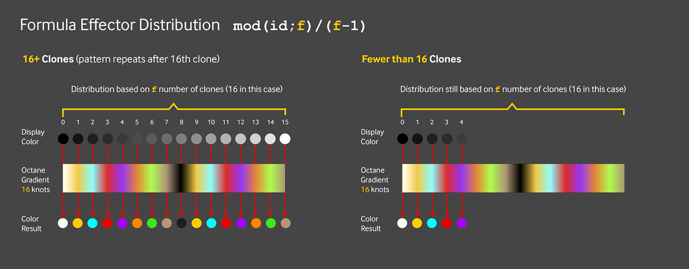
Essentially what’s going to happen here is that rather than split the grays up evenly across all the clones in the cloner like the step effector does, the formula effector with this fancy modulo formula will take a number we give it in the variable field (called f), divide the 0-1 scale up using that number to get an increment, and then add that increment to the previous clone’s value until it runs out of clones.
If there are fewer clones than the number we specified, it’ll still keep the distribution right, it’ll just stop when there are no more clones. If there are more clones than the number we specified, it’ll loop back to the beginning and repeat perfectly.
Modulo is a somewhat complex thing that’s not super easy to understand if we don’t have a math brain and/or haven’t done much coding. Fortunately, we don’t need to - Paul van Sommeren was nice enough to figure it out for us (thanks, Paul!) :)
Let’s do this

Let’s delete the Step effector, select our cloner and add a Formula Effector. As we well know by now (since it’s mentioned in every single YouTube tutorial on the Formula Effector), all hell breaks loose because of the big, scary, complex default formula.
First things first, let’s go into the effector’s Parameters tab and uncheck Position and Scale. Then let’s set the Color Mode to Effector Color and uncheck Use Alpha/Strength. We only want it affecting the color, not the position/scale/rotation.
Now let’s go back to the Effector tab, and roll down “Variables”. At the very bottom, there are two variables. The formula that we’re going to use references the f (frequency) variable. It’s set up like this so we don’t have to directly modify the actual formula every time we use it. “Frequency” is just the default name for it, we can put anything we want in there, frequency or otherwise. Our formula uses f in a way that will determine the number of different grays we want to use. In our case, we have 16 textures and 16 knots on our color gradient, so we need 16 different grays to map these to. Let’s put 16 in the box next to f-frequency.
Finally, the formula. Let’s copy this...
mod(id;f) / (f-1)
...and paste it in the “Formula” box and hit enter.
mod is the modulo function. id is the clone id. f is the variable we set in the last step (16).
Now the distribution is correct and we get the right colors again, only this time we can have as few or as many billiard balls as we want, and the colors and numbers will always be right (remember that the multishader uses the same gray distribution as the color shader, so this was messing our numbers up in addition to the colors).

We can test this by setting the cloner back to grid and scrubbing through the number of clones on any axis - it always repeats properly now. Yay!
Re-racking
Let’s set the cloner back to Object mode and re-link our polygon if need be.
All the balls have the correct color and labels, but a triangular polygon with 4 segments produces 15 vertices, and we have 16 ball textures, so we’re missing the 15-ball (the last one in the set). Also, the cue ball is in the rack, which is a problem if we want to play the game properly.
First, we need to hide the cloner and show the Polygon so we can see what we’re doing.

Now let’s get a 16th vertex in there. We can do this pretty quickly by making the Polygon editable (C key on the keyboard with the Polygon selected), then going into Points mode. Using the Live select tool to select the topmost point, we can control (command on mac)-drag the blue (Z) handle up a bunch. Control/Command-dragging duplicates the point, so now we have 16 total.
When we make the cloner visible and hide the polygon again, we’ll see that we have all 16 of our balls again (thanks to our polygon object now having 16 points), but they’re in the wrong order.
Custom Order with a Spline
There are a lot of schools of thought on proper 8-ball racking. No matter what we do here, some pedant will probably tell us we’re wrong. To be safe, we’re going to go by the International Billiards Association rules, which wants a solid up front, a stripe in one bottom corner and a solid in the other. 8 in the middle, of course (we’re not animals).
There are a few ways to plot the exact location of each clone. The math portion of our brains are already fried from all this formula stuff, so we’re going to go for a quick and dirty way using a spline.

Let’s get into the top view, make the polygon object visible (since we’ll be snapping to this) and hide the cloner to reduce visual clutter.
Great, next up let’s turn on Snapping at the top of the interface (or side if you’re using S24 or earlier). In the snapping settings, we want Snap enabled, Auto Snap on, Point turned on.
Now let’s pull up this diagram in the assets folder so we know what point order to draw in.
Remember, start with point zero (The cue ball). After that, the point order is the same as the ball numbers, so that’s easy. Using the Spline Pen, we can just hover over the location of the ball we want until we see the snapping indicator and then place a point. When we’re done, we get this crazy zigzag pattern, but the important part is that the point order is set up to place the balls where we want. We can rename the spline Ball Order Spline.

Time to link this up - let’s click the Cloner, and drop the Ball Order Spline in the Object field. The Distribution needs to be set to Vertex, and Align Clone needs to be turned off so the balls aren’t taking on the orientation of the points.
Sweet!
Wrap Up
We covered a lot of ground here, but hopefully you have a better understanding of how to use mograph tools with Octane.


